Series cover. The Poincaré-sphere motif represents pixelwise polarization reachability; it is an original explanatory graphic rather than a figure reproduced from the paper.
Series 01 — the fixed-input case
This article discusses F. Kenny et al., “Complete polarization and phase control for focus-shaping in high-NA microscopy,” published in Optics Express in 2012.
A spatial light modulator (SLM) is often introduced as a programmable phase plate. That description is adequate for a scalar field with a fixed polarization, but it is incomplete in high-numerical-aperture microscopy. At high NA, the polarization distribution across the entrance pupil affects the longitudinal electric field, the focal intensity, and the local polarization structure.
The paper therefore asks a more demanding question:
Given a known, fixed, and fully polarized input, how can we prescribe the polarization state independently at every point across the beam?
The result in one paragraph
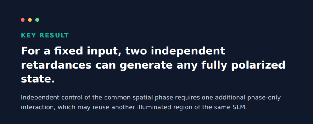
Two variable retarders with linearly independent axes can transform a fixed input polarization into any fully polarized output state. In the experiment, two parallel-aligned nematic liquid-crystal SLMs supply those retardances, while a double pass through a half-wave plate creates the required 45° difference between their effective axes. If the common spatial phase of the two Jones components must also be prescribed, the light needs one additional phase-only SLM interaction. This means two physical SLMs but three SLM interactions, because one device can be reused on a different illuminated region.
1. Polarization and common phase are different control targets
At a transverse position (\mathbf r=(x,y)), a fully polarized field may be written as
The pair () and () determines the local polarization ellipse. The factor () is a common phase multiplying both polarization components; it changes the scalar wavefront without changing the local polarization ellipse.
This separates the control problem into two layers:
| Control target | Independent quantities | Physical role |
|---|---|---|
| Local polarization | 2 | Sets the ellipse orientation, ellipticity, and handedness |
| Common spatial phase | 1 | Sets the scalar wavefront shared by both Jones components |
The paper uses the term “absolute phase.” In a modern explanation, it is safer to call this quantity the common spatial phase relative to a consistent reference. An optical carrier phase is not observable without a reference.
2. Why one fixed-axis SLM is generally insufficient
Each pixel of a parallel-aligned nematic SLM is approximated as a lossless linear retarder with a fixed eigenaxis and a programmable retardance. A convenient Jones model is
where () is the active-axis orientation and () is the programmed relative phase delay.
On the Poincaré sphere, varying () rotates the Stokes vector around a fixed equatorial axis. A single fixed-axis device therefore moves the input state along one circle; it does not, in general, cover the full sphere.
A second, independent rotation axis changes the geometry. The 2012 system uses two effective retarder axes separated by 45° in real space. Because linear-polarization azimuths appear with a doubled angle on the Poincaré sphere, those axes are orthogonal on the sphere. Their two programmable retardances are sufficient to reach any fully polarized output from the prescribed input.
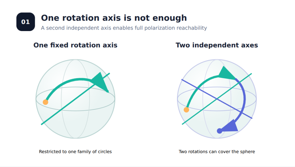
Figure 1. One fixed-axis retarder restricts the state to a circle. A second independent axis enables full polarization-state reachability for a prescribed input.
3. What the two retardances do
The experiment starts from a spatially uniform vertical linear polarization. The two SLMs apply spatially varying delays ()) and ().
A useful physical interpretation is:
- () controls how the field is distributed between two orthogonal polarization components;
- () controls their relative phase;
- together they determine the orientation, ellipticity, and handedness of the local polarization ellipse.
Because the calculation is local, the same transformation can be performed pixel by pixel. Spatially varying delay maps generate a spatially varying vectorial field.
The scope must be stated precisely: this is complete polarization control for a known, fixed, fully polarized input. It is not yet a universal transformer from an arbitrary input vectorial state to an arbitrary output vectorial state.
4. How the 2012 experiment was built
The work includes a real optical experiment rather than only a Jones-matrix argument. The principal components reported in the paper are summarized below.
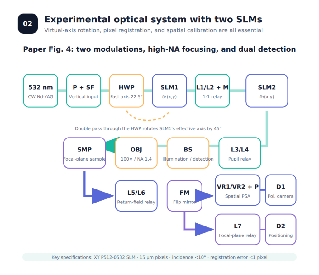
Figure 2. Explanatory redraw of the reported 2012 apparatus. The labels are in English; the geometry is simplified and should not be interpreted as a scale drawing.
| Subsystem | Reported implementation | Function |
|---|---|---|
| Source | Melles Griot 85-GCA-005-100, 532 nm continuous-wave frequency-doubled Nd:YAG laser | Monochromatic coherent illumination |
| Input preparation | Calcite polarizer, beam expansion, and spatial filtering | Produces a clean vertical linear input |
| Modulators | Two Boulder Nonlinear Systems XY P512-0532 parallel-aligned nematic SLMs | Apply () and () |
| Pixel pitch | 15 µm | Sets the registration tolerance between conjugate SLM planes |
| Axis transformation | Half-wave plate with its fast axis at 22.5°, traversed twice | Produces a 45° effective axis difference while keeping the SLM pixel grids parallel |
| Relay | L1/L2 and a folding mirror, 1:1 imaging | Conjugates SLM1 to SLM2 |
| Objective | Olympus UPLSAPO 100× oil-immersion objective, NA 1.4; immersion index 1.518 | Produces the high-NA vectorial focal field |
| Main detection arm | VR1, VR2, a linear polarizer, and camera D1 | Spatial polarization-state analysis and calibration |
| Auxiliary arm | Flip mirror, L7, and camera D2 | Focal-plane observation and sample positioning |
Optical sequence
- The 532 nm beam passes through the calcite polarizer, beam expander, and spatial filter.
- It traverses the half-wave plate, reflects from SLM1, and traverses the same plate again.
- L1, L2, and the folding mirror relay the SLM1 plane onto SLM2 at unit magnification.
- L3 and L4 image the modulated polarization distribution onto the entrance pupil of the high-NA objective.
- The returned or scattered field is directed to either the polarization-analysis camera D1 or the focal-plane camera D2.
The paper notes quasi-normal incidence for the SLMs and cites a manufacturer recommendation of less than 10°. Values not reported in the paper—such as every lens focal length, camera model, or mechanical separation—should not be inferred from the schematic.
Why the half-wave plate matters
The double pass through the 22.5° half-wave plate makes the first SLM act as though its modulation axis were rotated by 45° relative to that of the second SLM. This “virtual axis rotation” provides independent retardance axes without physically rotating the square pixel arrays. The pixel grids can therefore remain parallel and be registered point by point.
Why the 1:1 relay matters
The two SLM planes must be optically conjugate. The paper specifies registration within one pixel, or 15 µm. If the delay maps are laterally misregistered, () and () no longer act on the same spatial sample, and the local two-retarder model breaks down.
D1 and D2 have different jobs
The D1 arm contains two variable retarders separated by 45° and a linear polarizer. It is a spatial polarization-state analyzer, not simply an intensity camera. The D2 arm images the objective focal plane and is used for positioning and for observing the two-spot and four-spot patterns.
Calibration is part of the method
The illumination and detection optics introduce spatially varying polarization errors. The authors use an eigenvalue calibration method (ECM) to estimate and remove these errors across the beam. The theoretical statement that two independent retardances are sufficient does not remove the experimental need for registration and calibration.
5. What was demonstrated at the focus
The authors use a vectorial high-NA propagation calculation based on the McCutchen method and compare it with representative measurements.
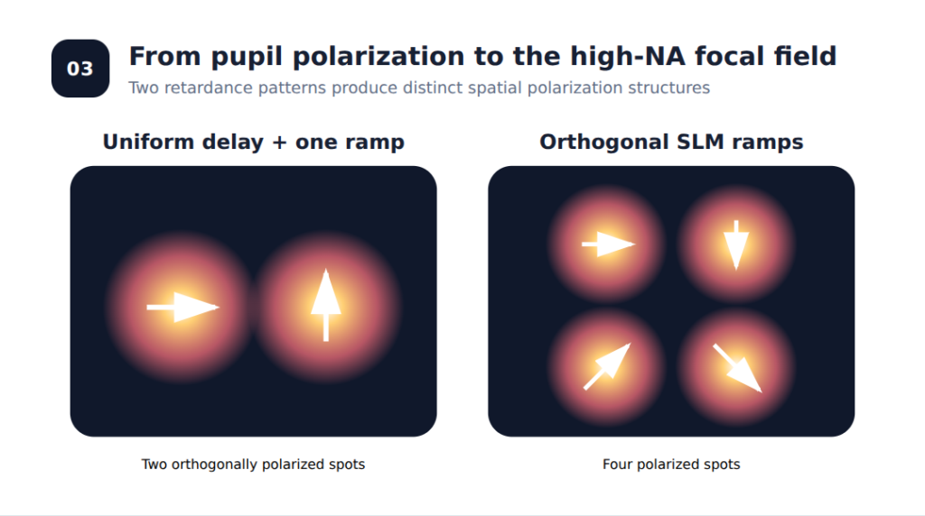
Figure 3. Conceptual reconstruction of the two-spot and four-spot demonstrations. It illustrates spot count and polarization orientation, not measured intensity pixels.
Two orthogonally polarized spots
SLM1 carries a uniform () delay, while SLM2 carries a wrapped retardance ramp with five periods. The focus separates into two spots with orthogonal polarizations.
This example does not, by itself, demonstrate the full spatial capability of both SLMs because the uniform delay on SLM1 could be replaced by an ordinary retarder.
Four polarized spots
The two SLMs carry orthogonal wrapped retardance ramps, each with ten periods. The focal plane then contains four spots. This example genuinely uses spatial modulation on both devices.
The numerical example in the paper uses NA 0.95, whereas the experiment uses the 100×, NA 1.4 oil-immersion objective. The theoretical and experimental panels should therefore be interpreted as validation of the spot count, separation direction, and polarization structure—not as pixel-for-pixel intensity reproductions under identical sampling conditions.
The paper also calculates a three-dimensional vectorial focal field with a Zernike trefoil structure. That result is theoretical; it should not be described as an experimental demonstration.
6. Why common-phase control needs another interaction
Two SLM retardances determine the polarization state, but they do not independently prescribe the common phase of the two Jones components. The extended architecture can be represented schematically as
The sign of () depends on the chosen time-harmonic and device convention; the physical point is that it multiplies both output components equally.
The proposed arrangement still uses two physical SLMs, but the beam interacts with SLM surfaces three times:
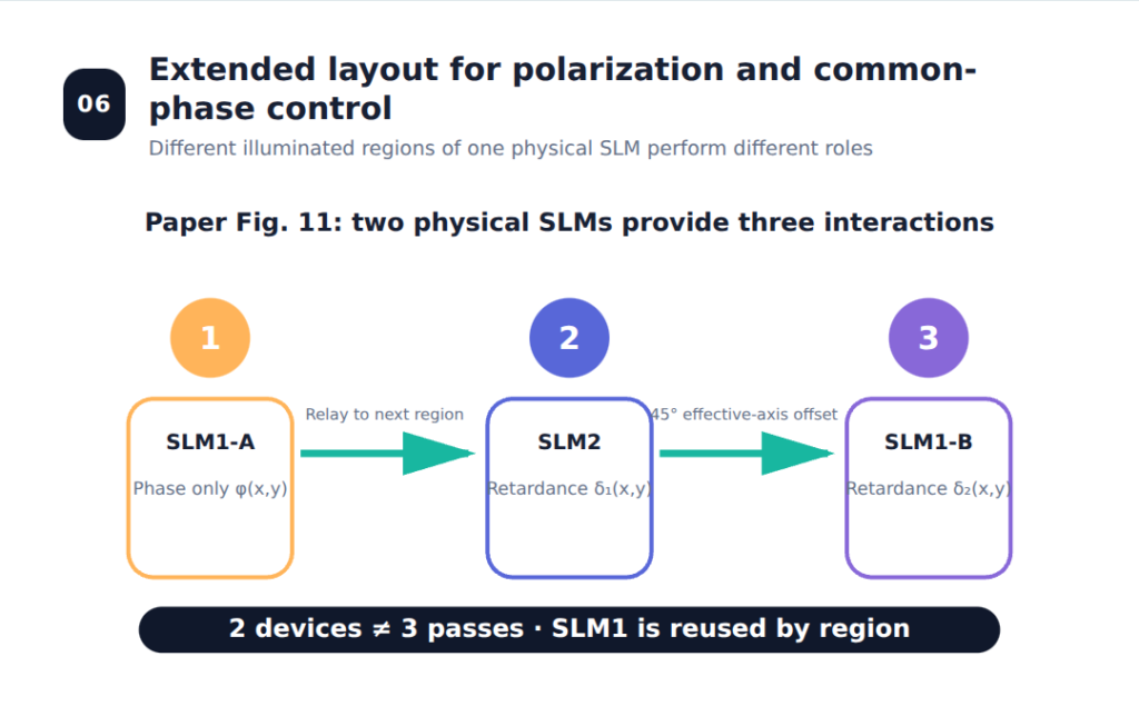
Figure 4. The distinction between physical-device count and optical-interaction count. A separate illuminated region of SLM1 is reused for the third interaction.
- On the first interaction, the incident linear polarization is aligned with the active axis, so the SLM region writes only the desired common spatial phase ().
- Two subsequent interactions provide the independent retardances () and ().
- A different illuminated region of the same physical SLM can be reused for the third interaction.
This distinction is essential:
| Quantity | Count in the extended design |
|---|---|
| Physical SLM devices | 2 |
| SLM interactions or passes | 3 |
| Programmed scalar fields | (,,) |
The first phase-only interaction may also compensate a conventional wavefront aberration, provided the required phase range and calibration accuracy are available.
7. What the paper established—and what it did not
Established by the paper
- Two independent programmable retardances can generate arbitrary spatial polarization from a fixed input.
- A double-pass half-wave plate provides the required effective axis rotation while preserving pixel-grid registration.
- The concept was implemented with two SLMs, a high-NA objective, spatial polarization analysis, and ECM calibration.
- Spatially separated orthogonally polarized focal spots were demonstrated.
- An extended two-device, three-interaction layout was proposed for joint polarization and common-wavefront control.
Not established by the paper
- Universal conversion from every arbitrary input vectorial state to every arbitrary output vectorial state.
- Independent spatial-amplitude control.
- Broadband or achromatic operation.
- A closed-loop model including pixel crosstalk, zero-order leakage, oblique-incidence effects, and long-term drift.
- Experimental realization of every calculated high-NA field, including the Zernike-trefoil example.
8. Engineering extensions
The following are logical extensions, not results reported in the 2012 paper:
- jointly calibrate grayscale-to-retardance lookup tables, incidence angle, pixel crosstalk, and fixed phase offsets;
- use camera feedback to update the delay maps in a closed loop;
- combine polarization-aberration correction with conventional wavefront correction;
- add amplitude encoding or interferometric degrees of freedom when the target includes an arbitrary complex amplitude;
- calibrate the liquid-crystal and wave-plate dispersion separately for multiwavelength operation.
Takeaway
Two independent SLM retardances solve the local polarization problem for a fixed input. A separately programmable common wavefront requires another optical interaction, even when that interaction reuses one of the same two physical devices.

The next article removes the fixed-input assumption and asks why three SLM interactions can reach any target polarization yet still fail to provide an arbitrary output phase.
Reference
F. Kenny, D. Lara, O. G. Rodríguez-Herrera, and C. Dainty, “Complete polarization and phase control for focus-shaping in high-NA microscopy,” Optics Express 20(13), 14015–14029 (2012). https://doi.org/10.1364/OE.20.014015